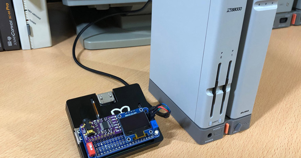
X68uartRasModuleの組み立て
作業は自己責任でお願いいたしますです。
 うさっぴ
うさっぴ注意だぴょん。自己責任にてお願いするだぴょん。
当サイトに掲載された内容によって生じた損害等の一切の責任を負いかねますのでご了承ください。だぴょん。
※このブログについてのプライバシーポリシー
 パンだ
パンだあくまでこのブログの主の番長は独学でトライアルアンドエラーを繰り返してるだけの素人だパンだ。ときにはしくじって電子機器をぶっこわしたりもしています。ご理解いただいた上でお楽しみくださいだパンだ。
 ぴぽこ
ぴぽこよろしくお願いいたします。
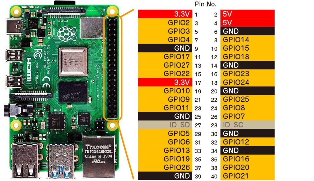
使用するGPIOのおさらい
GPIOのピン配置確認
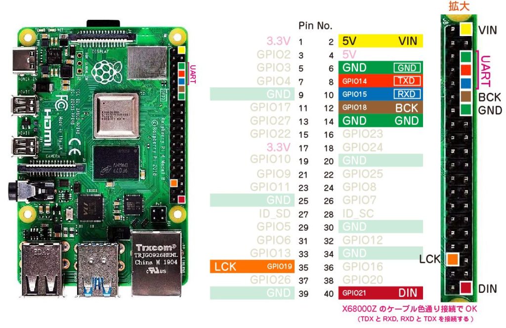
UART/DAC (PCM5102) のGPIOのピン配置確認
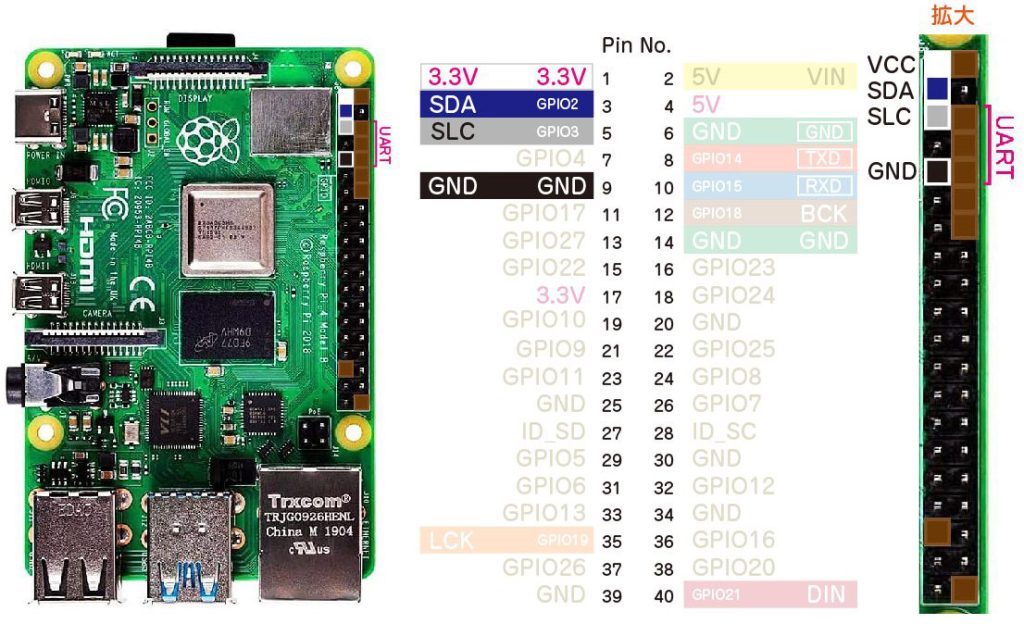
LCDモニター (SSD1306) のGPIOのピン配置確認
GPIO23番にLED、GPIO26番にスイッチを追加します。
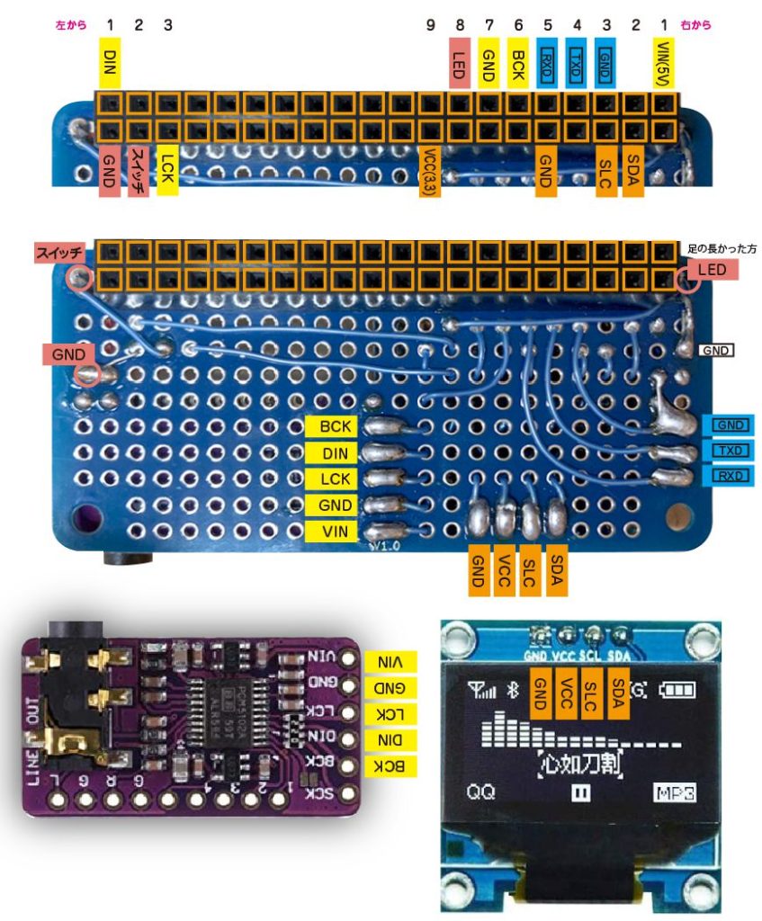
配線図
 ねこっぴ
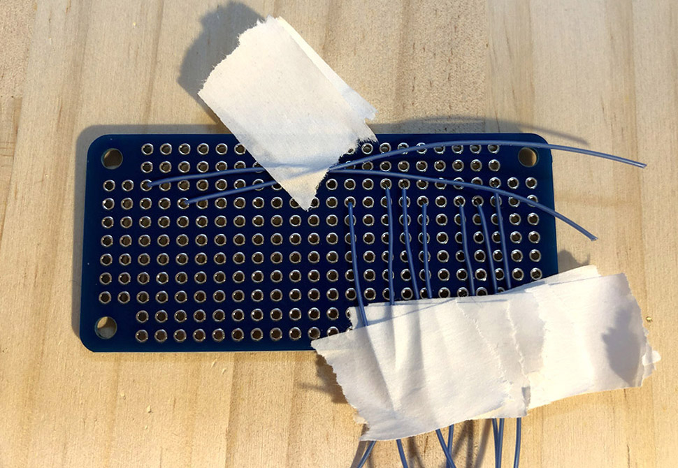
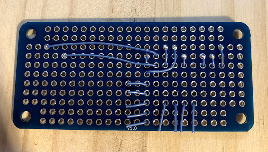
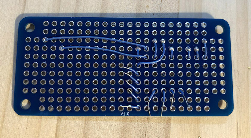
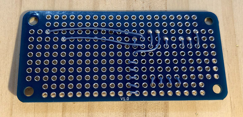
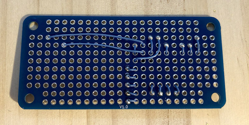
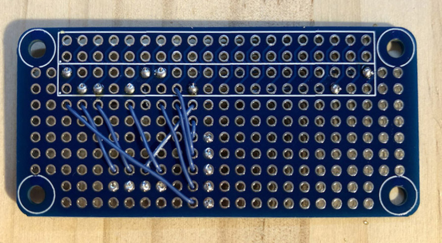
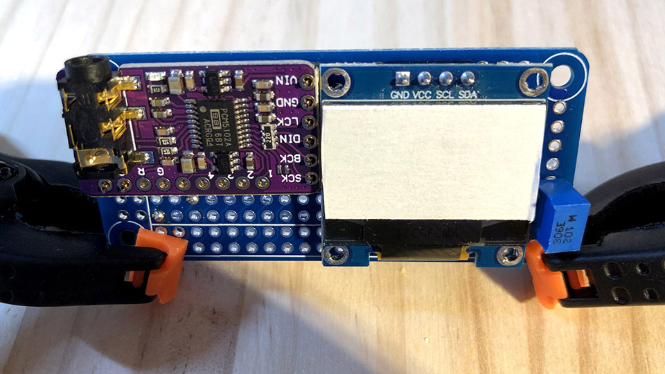
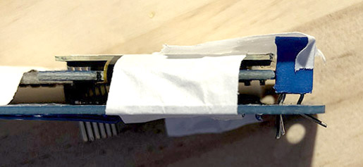
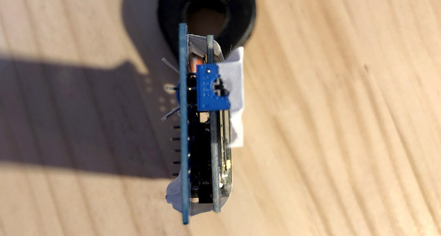
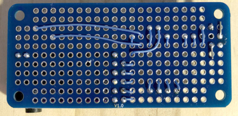
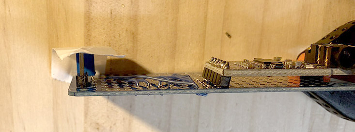
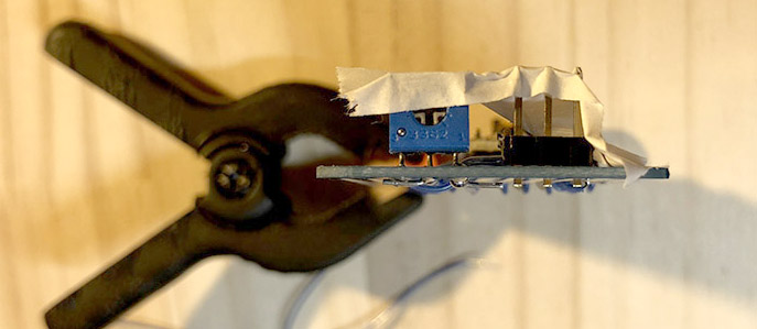
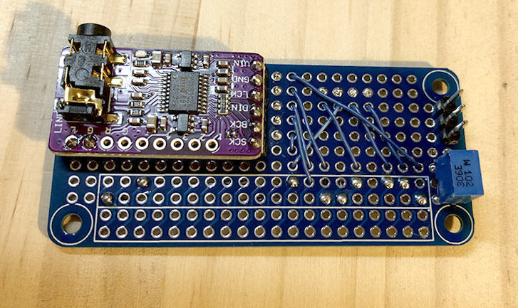
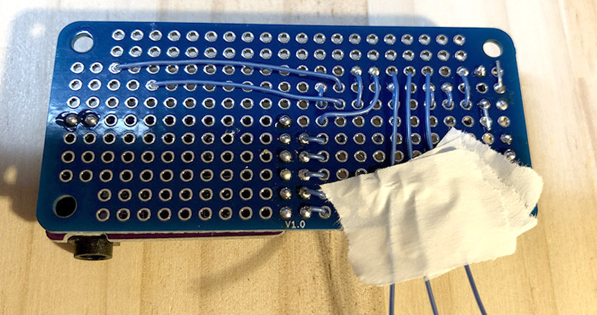
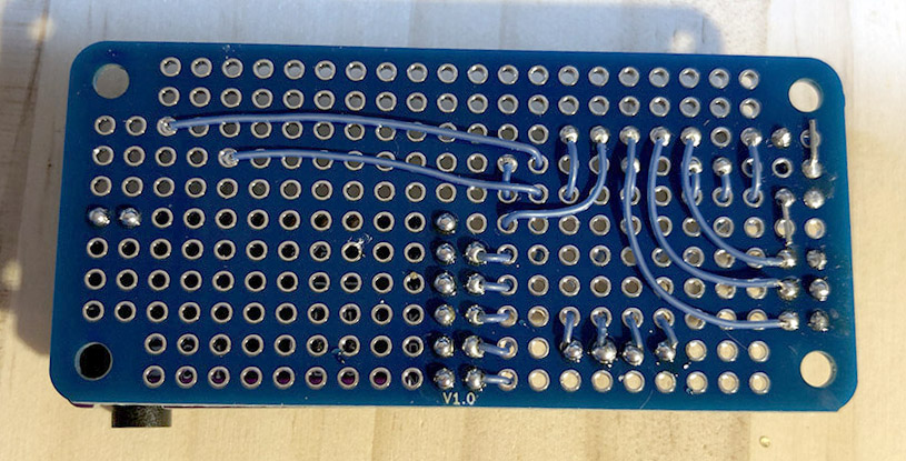
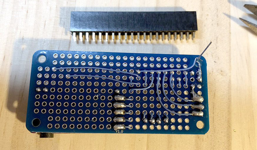
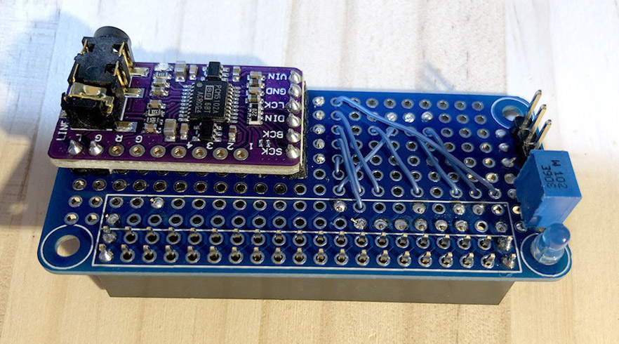
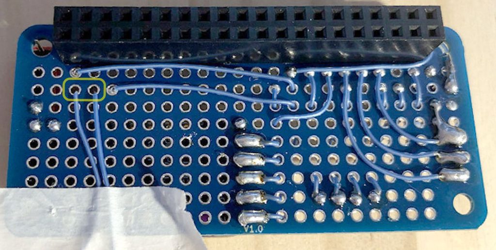
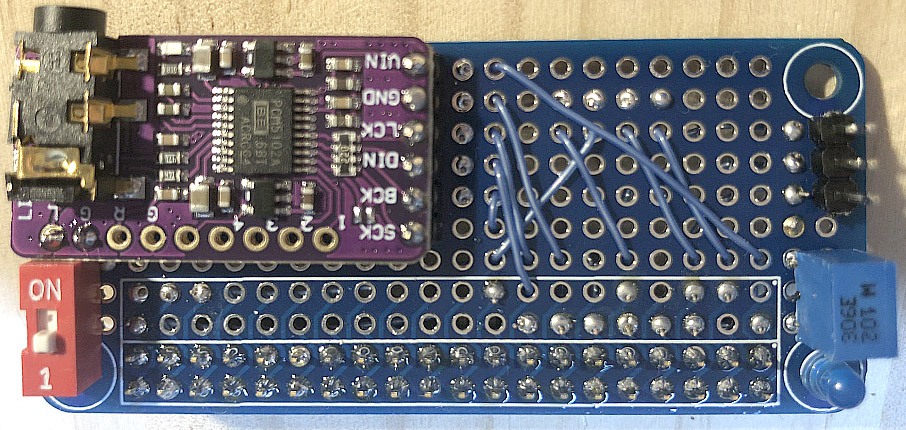
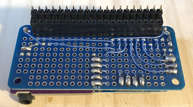
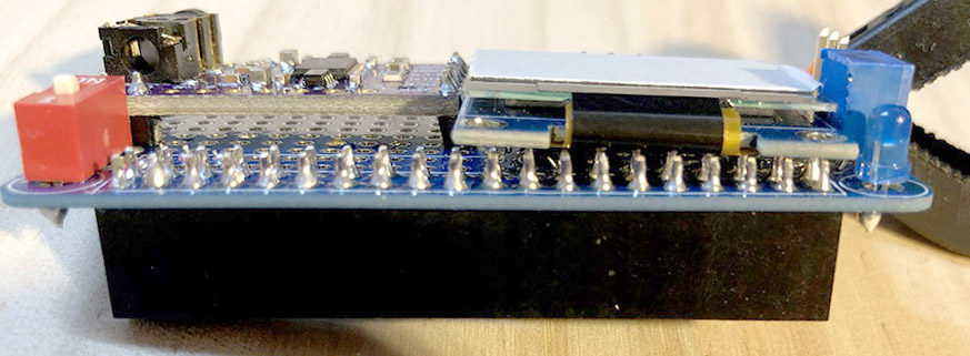
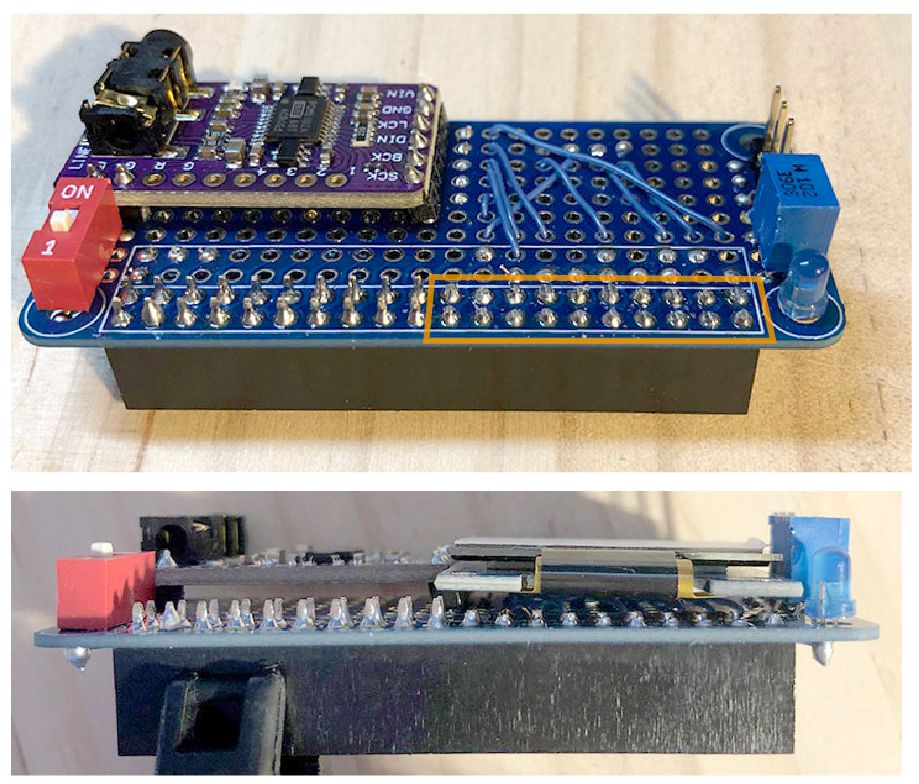
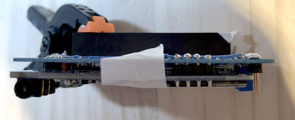
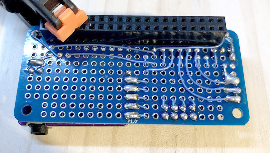
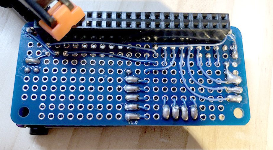
ねこっぴ配線図と完成した基板の写真にゃよ!
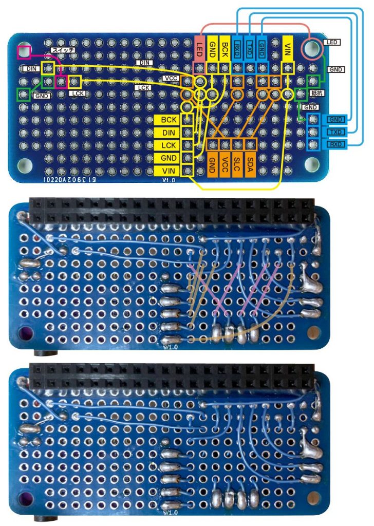 ぴぽこ
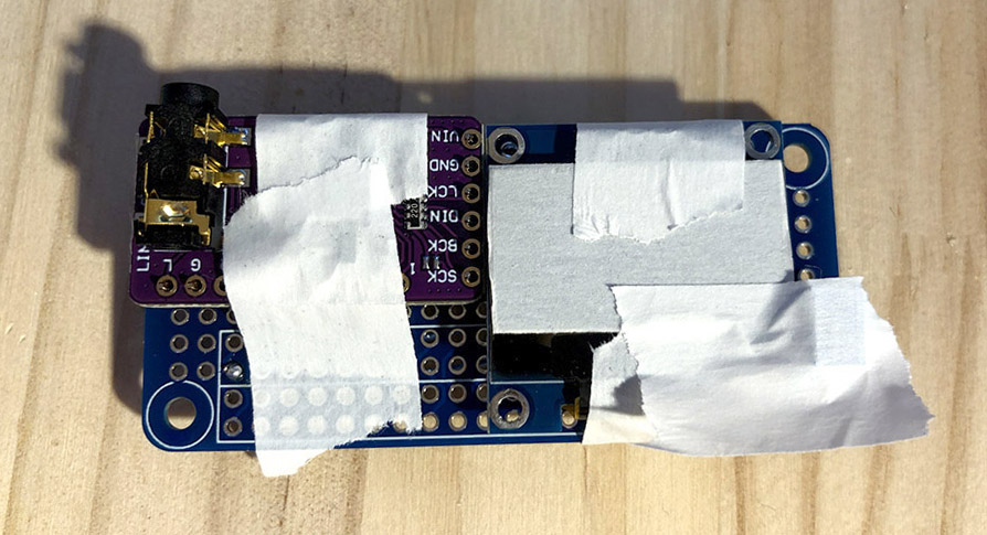
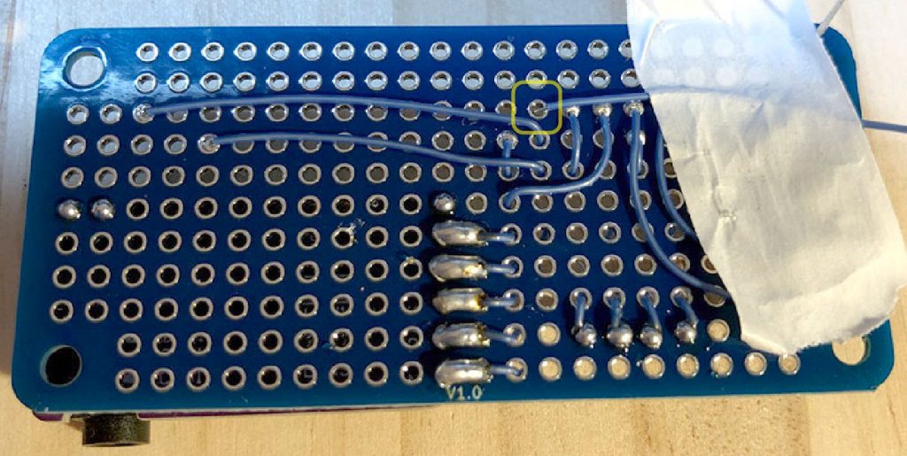
ぴぽこ基板の表裏にコードを通したりしています。真ん中の写真が裏で繋がっている位置図。一番下の写真と見比べてみてね。
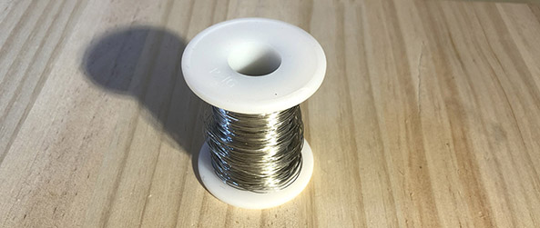
コードのカットと皮むき
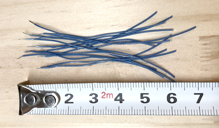
ねこっぴコードをカットするにゃ。基板の横幅ぐらいのを13本。
片側だけ皮向いてね。皮むき部分は多いとやりやすいかにゃ。
モニターとDAC部分の配線
ねこっぴモニターとDAC部分の配線をするにゃ。
 ねこっぴ
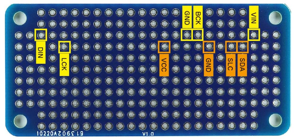
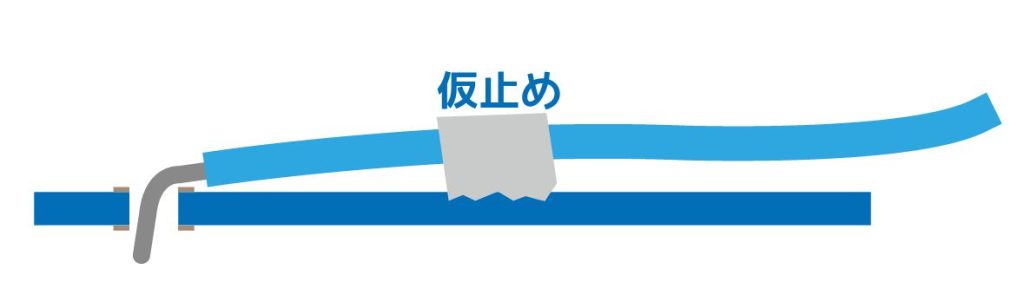
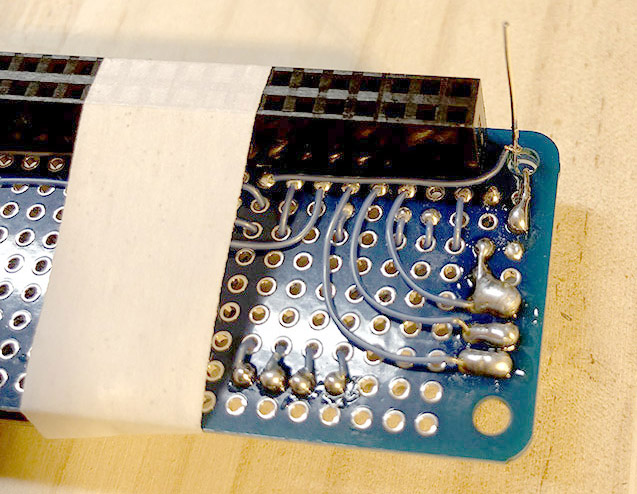
ねこっぴ各箇所の基板の穴に絵のようにコードを配置して仮止め。反対側からはんだ付けするにゃよ。
 ぴぽこ
ぴぽこはんだ付けしたあと長く飛び出てしまったら飛び出た部分はカットしてね。
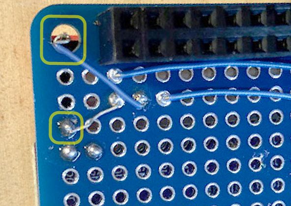
ねこっぴ再度ひっくりかえして配線図のようにくぐらせるにゃ。
 ねこっぴ
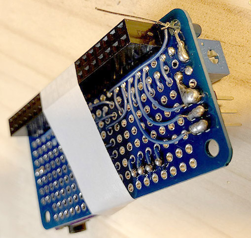
ねこっぴまたまたくるりと回して通すにゃ
 ねこっぴ
ねこっぴくるくる作業にゃ。コードを揃えてカット。皮むきするにゃよ!
 ぴぽこ
ぴぽこここでピンセット大活躍!
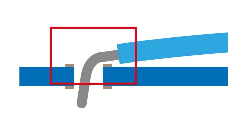
写真のように皮向いた部分が顔のぞいてるとGOOD!
 ねこっぴ
ねこっぴ皮むき部分の位置調整をするときに裏側に配線押し込んで裏側配線フワってしててもむしろモニター支える土台になるから大丈夫。
こちらの面からはんだ付けにゃ!!
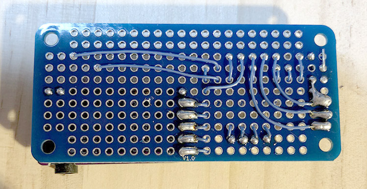
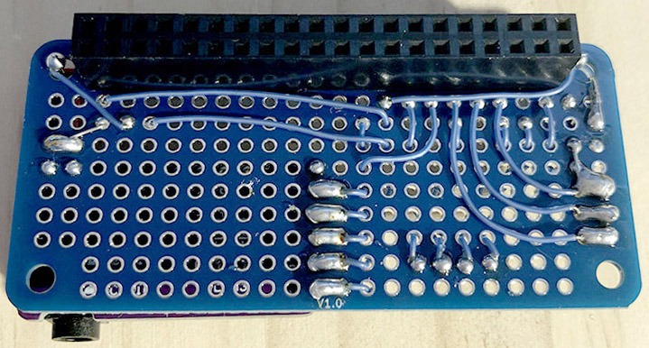
 ねこっぴ
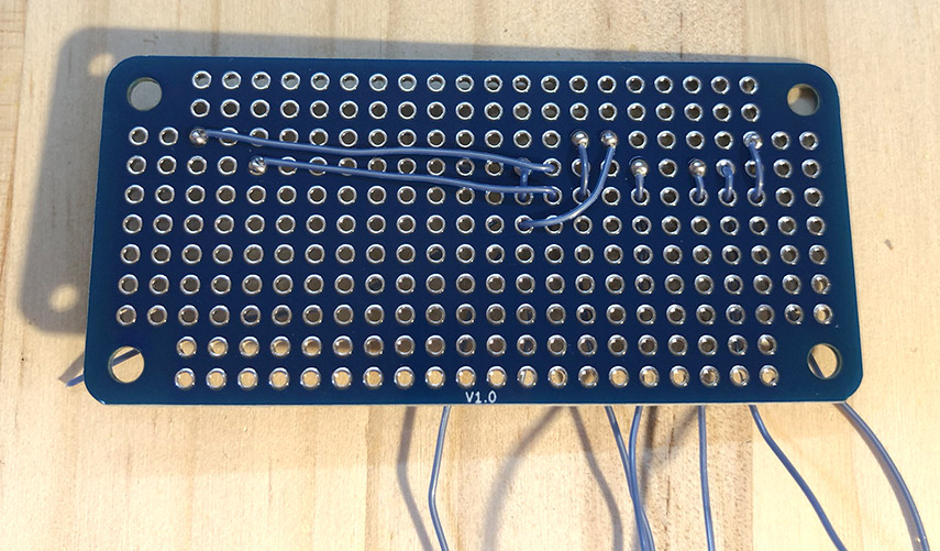
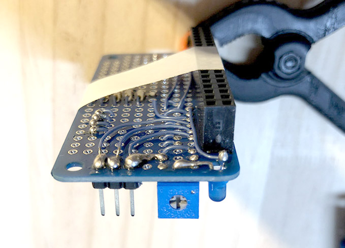
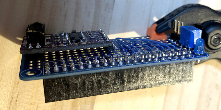
ねこっぴひとだんらくにゃ。休憩時間。ちな 反対側の図。
モニターとDACと抵抗の位置決め
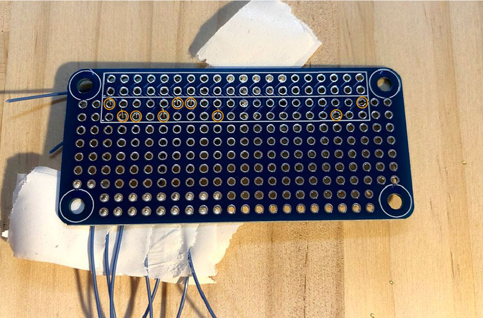
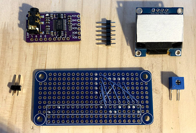
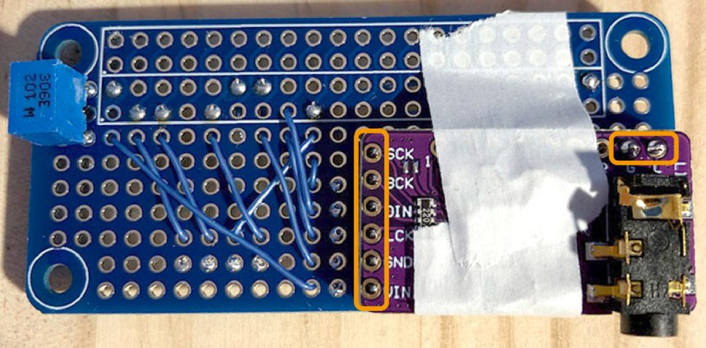
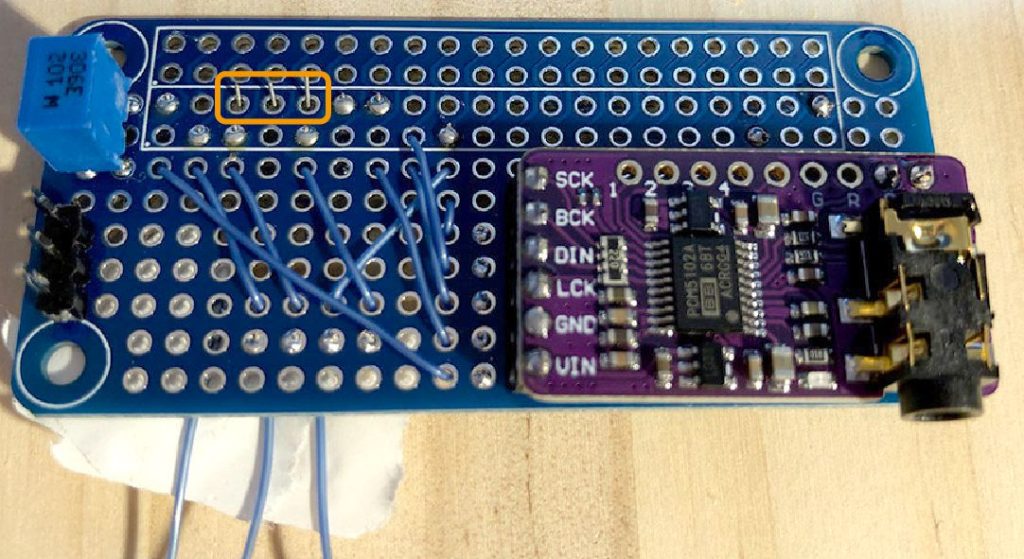
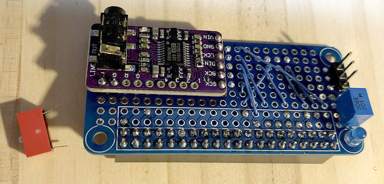
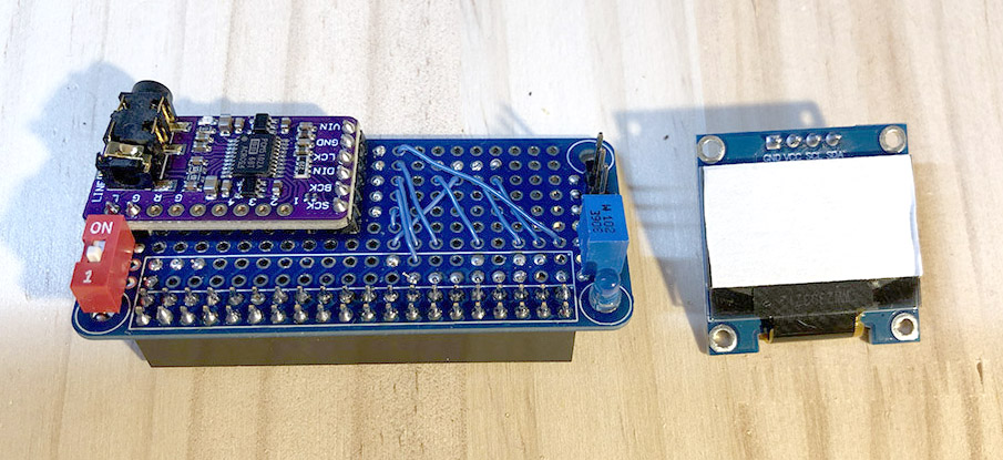
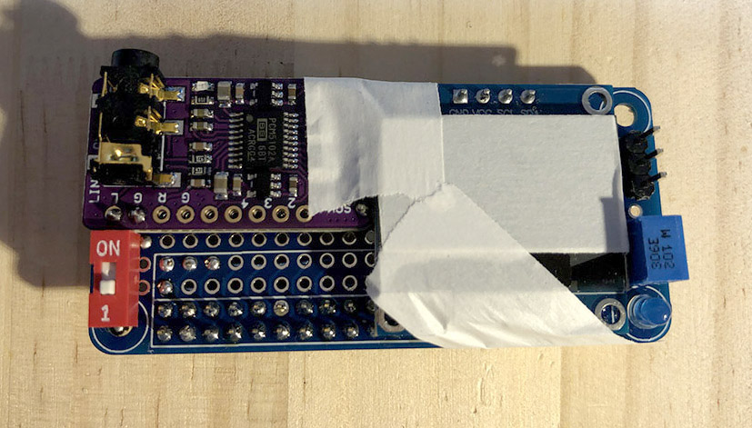
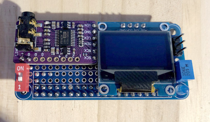
ねこっぴモニターとDACの位置決めするにゃ。ロット?メーカー? わからにゃいけどモニターのサイズに微妙な違いがあるようで、このへんを調整するにゃ。写真の6本足のピンヘッダは、DACのSCKを使わないので5本足にしてもOK。2本足のピンヘッダは強度のために使用。電気的には接続しないにゃよ。モニタの保護フィルム剥がれちゃったらテープで保護しとこ。
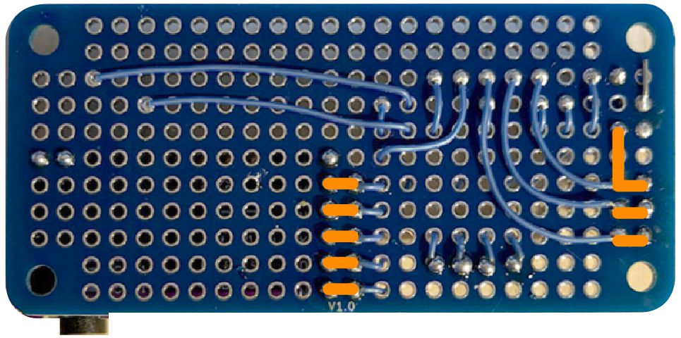
 ぴぽこ
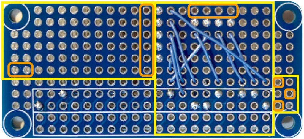
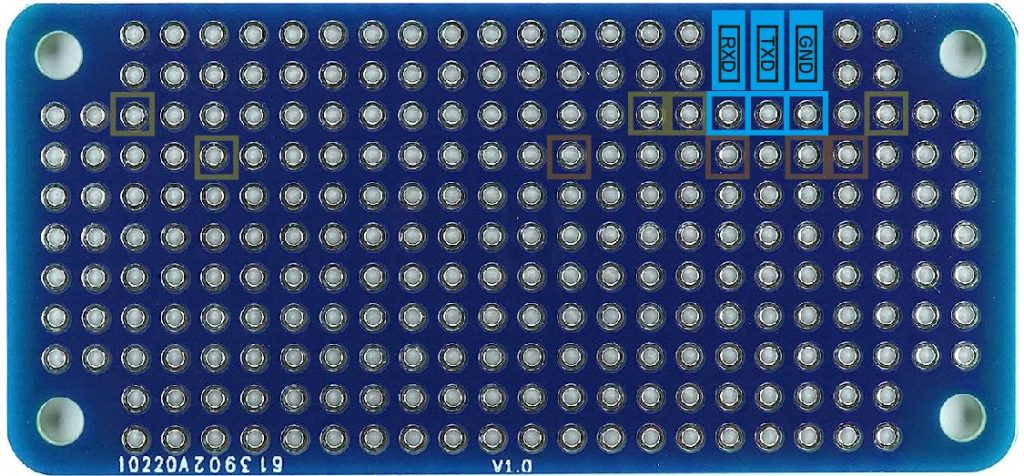
ぴぽこモニターとDACと抵抗の設置位置はここ! オレンジがピンの位置です。
 ねこっぴ
ねこっぴ抵抗がモニターに押されるようだったら足をくにゃっとさせてバランスよくしよー
 ねこっぴ
ねこっぴマスキングテープで位置ロック。
 ねこっぴ
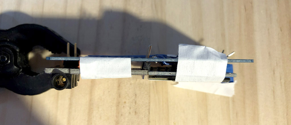
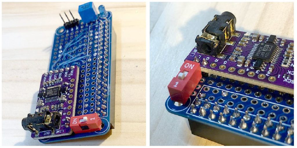
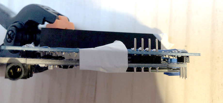
ねこっぴモニターの幅によってはDAC位置を調整。下の写真のように斜めじゃなくてもキレイに設置できるなら2本足のピンヘッダを1本足にして調整したり柔軟に対応にゃ。
DACと抵抗をはんだ付け
ねこっぴDACと抵抗だけハンダ付けするにゃ モニタのハンダ付けは最後の最後。DACは基板側とDAC側どっちもハンダ付けにゃよ。
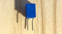
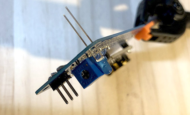
ぴぽこまずは抵抗のハンダ付けからいこー。写真のように足をまげてハンダ付けしてね!
 ねこっぴ
ねこっぴ次はDAC。飛び出てる足が長いとハンダ付けしずらいので1mmぐらい基板から出る感じでカットしてからのほうがらくかにゃ。
 ねこっぴ
ねこっぴモニターをはずしてDAC基板のハンダ付けにゃ。
UART端子用ピンの取り付けと配線
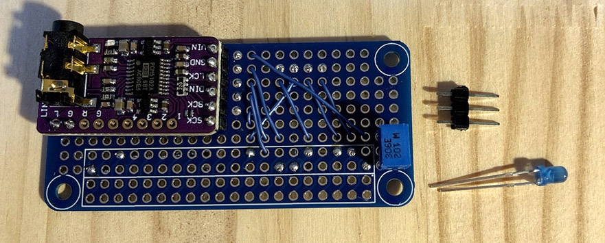
ねこっぴまずはUARTピン。LED写真にあるけど後回しにゃ。
 ねこっぴ
ねこっぴまっすぐ状態をマスキングテープで保って裏からハンダにゃよ!
 ねこっぴ
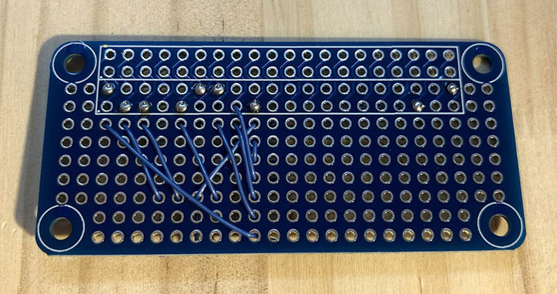
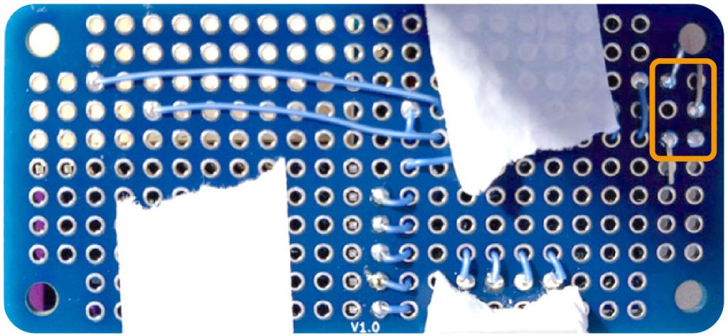
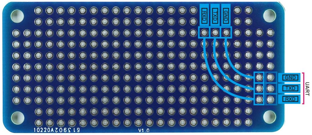
ねこっぴUARTの3本配線するにゃよ。コードを仮止めして裏からハンダにゃ。
 ねこっぴ
ねこっぴくるっとすると、ここにゃ! ハンダ付けしたら飛び出た頭カットにゃよ。
 ねこっぴ
ねこっぴUARTピンにつなげますよ! 1つ手前にハンダ付けしてハンダもりもりで繋ぐ予定にゃ。自信がある人は直接ピンにハンダでもOK。
 ぴぽこ
ぴぽこここでピンセット大活躍!
絵のように皮向いた部分が顔のぞいてるとGOOD!
ねこっぴこちらの面からはんだ付けにゃ!!
 ねこっぴ
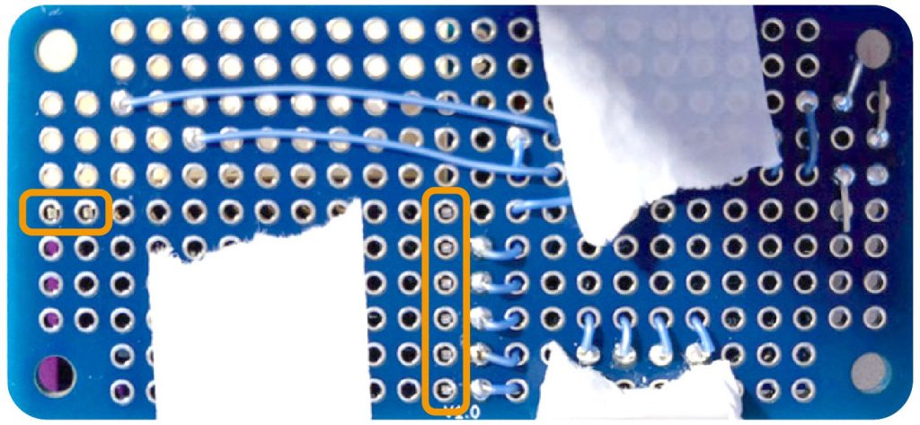
ねこっぴさてこのオレンジラインを繋げたいにゃ。手段ははんだメッキ線でもなんでもいいにゃ。ねこっぴは一番らくなハンダもりもりでいくにゃよ!
 ねこっぴ
ねこっぴもりもり完了。
 ねこっぴ
ねこっぴハンダもりもり結合ビデオ。こんなかんじでもりもりにゃ。
荒くてごめんね
LEDの取り付けと配線
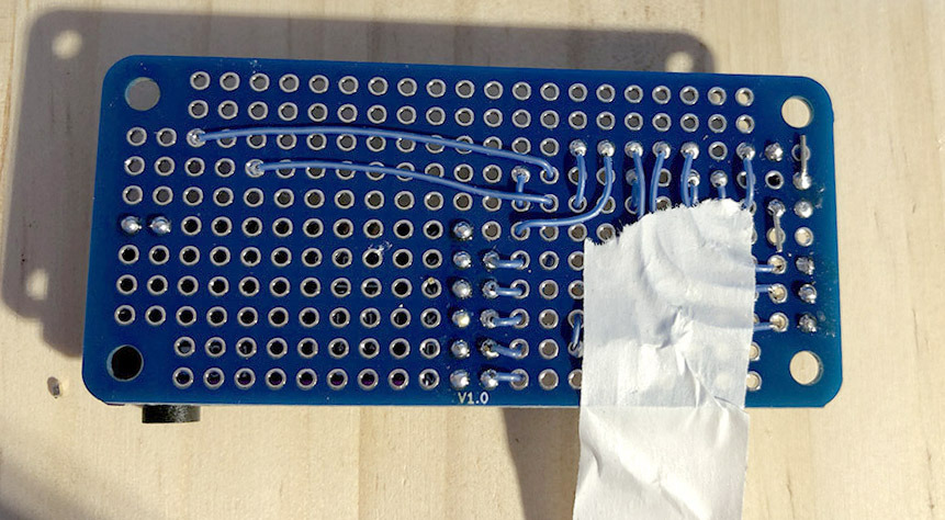
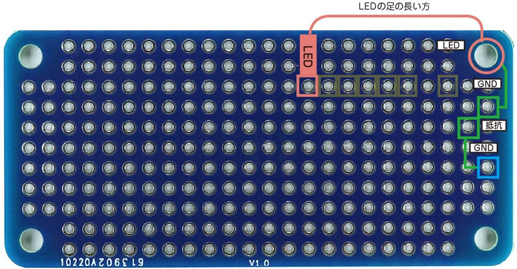
ねこっぴLEDをとりつけるにゃ。まず配線はこんな感じ。
 ねこっぴ
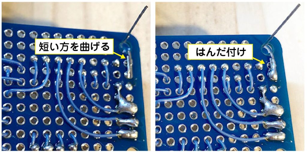
ねこっぴ短い足を曲げていい感じの位置でカット。はんだ付けしますよー。
 ねこっぴ
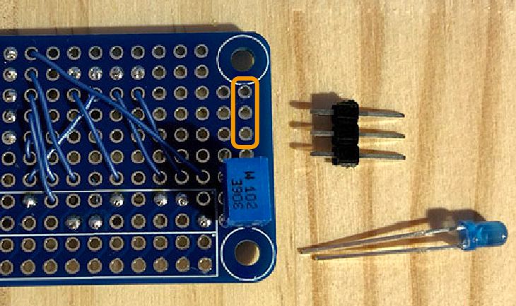
ねこっぴLEDの長い足に繋げるコードを基板にハンダ付けにゃ。
写真の方向で上から3個目右から10個目の位置。
 ねこっぴ
ねこっぴピンソケットにかぶらないように位置決めしつつハンダするにゃ。
 ぴぽこ
ぴぽこハンダ付けしてカットしました!
 ねこっぴ
ねこっぴ次はピンソケットをハンダ付けにゃ! テンポ良く根気良くがんばろー!
ぴぽこ最初に左右4本ハンダ付けしてロックしてからやるといいね!
 ぴぽこ
ぴぽこ40箇所ハンダ付けかんりょー!!
スイッチの取り付けと配線
ねこっぴスイッチをとりつけるにゃ。
 ねこっぴ
ねこっぴ配置はこんなかんじ。
 ねこっぴ
ねこっぴコードをここにはんだ付けにゃ。
 ねこっぴ
ねこっぴ写真でいうとスイッチの上側を右のコードと接続。
スイッチの下側を左のコードと接続。
左のコードは距離が短いので全部剥いちゃってもいいし、はじめからはんだメッキ線でもいいかにゃ。
 ぴぽこ
ぴぽこハンダ付けおっけー!! あとはモニターつけたら終わりだよ!!
 ねこっぴ
ねこっぴでも、モニターつけたあとに配線にミスがあったらめんどいので先に配線のチェックと導通チェックしよ!
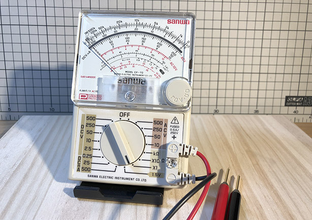
目視チェックと導通チェック
ねこっぴ配線の目視チェックと導通チェックにゃ。
ピンヘッダをソケットに挿してテスターでチェック!!
 ねこっぴ
ねこっぴ上の列、下の列順番に挿してチェックしましょー。
刺したピンヘッダとハンダした最終地点が繋がっているか、となりと接触していないか、念入りにチェック!
※モニターは現時点では基板の終点ハンダまでをチェック。モニターをハンダ後に再度チェックしてね。
モニターの取り付け
ねこっぴラストにゃー! モニター取り付け。モニターを取り付けたあとに配線ミスやハンダミスを発見すると電動ハンダ吸い取り器が無いとけっこーきついので注意ですよー。
ねこっぴモニターを載っけてみて、ハンダしたソケットに被る部分を少しカットするにゃ。心配ならカット後にモニターの裏にビニールテープとかで絶縁したほうがいいかも。
 ねこっぴ
ねこっぴそしたら位置決めして最後のハンダです!!
 ねこっぴ
ねこっぴ飛び出た部分は1mmほど残してカットしたほうがハンダしやすいよ!
 ねこっぴ
ねこっぴもりもりして….結合!!
完成!
ぴぽこおめでとーー!完成です!
 ねこっぴ
ねこっぴお疲れ様にゃ!
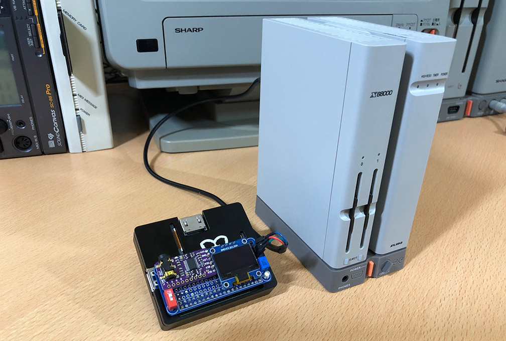
ラズパイの裏なんかにダイソーとかで売ってる色分けシール貼ればUART接続で迷いませんよー!
 ねこっぴ
ねこっぴ各ページの内容を見て動作チェックしてみてね!
ぴぽこLEDとスイッチはプログラミング編で説明しますね!
Pythonでモニターにいろいろ表示もできちゃうからお楽しみにねー!
・
・
・
- X68000Z UARTでなにができるの?
- X68000Zを動かしてみよう! X-Basic準備
- どのラズパイを選べばいいかな?
- ラズパイUART設定とケーブル接続
- ラズパイとのUART接続確認テスト
- MIDI再生専用FDを作成(mt32pi)
- MIDI再生専用FDを作成(ttymidi)
- mt32-piでラズパイをMIDI音源にする
- MIDIハード音源を試す
- DACとちびモニターを用意する
- X68uartRasModuleの製作 準備編
- X68uartRasModuleの製作 組立編
- アップデートとHDDの設定
- SX-Window HDDにインスト
- SX-Window MIDI演奏設定
- SX-Window MIDIハード音源設定
- プログラミング編 X-Basicになれてみる
- プログラミング編 Pythonに少し慣れてみる
- プログラミング編 UARTでX68kZからラズパイを操作!
- シェルスクリプトSW分岐とLチカ
- ちびモニタとLEDを制御する!
- ttymidiのUSBの関連付け自動
- Python実行形式にするPyInstaller
- Winkipedia/2chSC閲覧 X68k RasNet
- X68000Zの基本操作などのまとめ
- 番外編はTOPから!